
Lumens PTZ Camera Control
Lumens PTZ Camera Control with Crestron Processor Using RJ45 to RS-232 Connection
Lumens PTZ Camera Control with Crestron Processor Using RJ45 to RS-232 Connection
Introduction
In many Audio Visual (AV) installations, controlling a PTZ camera through a Crestron control processor is a common requirement. Most Lumens PTZ cameras support RS-232 control, allowing users to control camera functions such as Pan, Tilt, Zoom, Presets, and Tracking directly from a Crestron touch panel or control system.
This article explains how to connect a Lumens PTZ Camera to a Crestron Control Processor using the camera's RJ45 control port and the Crestron COM port (Phoenix Connector).
System Overview
The communication between the Lumens camera and Crestron processor is achieved through RS-232 serial communication.
Required Components
Lumens PTZ Camera
Crestron Control Processor (CP3, CP4, RMC4, etc.)
CAT6/CAT5e Cable
RJ45 Connector
Phoenix Connector (3-Pin)
Crestron Toolbox / Programming Software
Connection Diagram
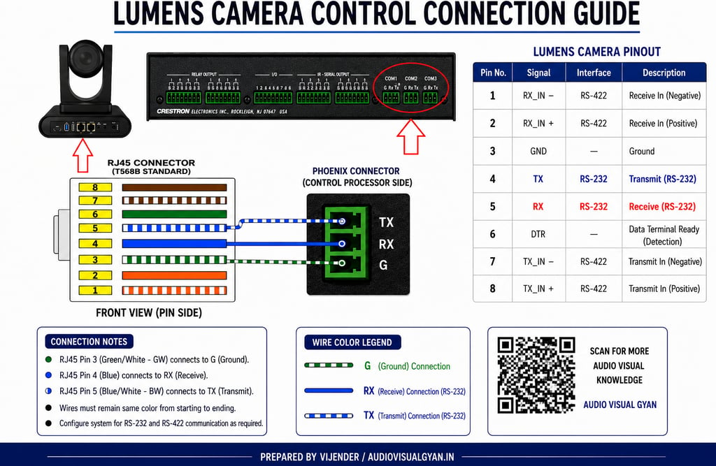
The Lumens camera RJ45 control port is connected directly to the Crestron COM Port using the following wiring configuration:
RJ45 PinWire ColorCrestron COM PortPin 3Green/White (GW)G (Ground)Pin 4BlueRXPin 5Blue/White (BW)TX
Phoenix Connector Side
G = Ground
RX = Receive
TX = Transmit
Wire Mapping
RJ45 Pin 3 (GW) ------------> G
RJ45 Pin 4 (Blue) -----------> RX
RJ45 Pin 5 (Blue/White) -----> TX
Lumens Camera Pinout Reference
Pin NumberSignalPin 1RX_IN – (RS-422)Pin 2RX_IN + (RS-422)Pin 3GNDPin 4TX (RS-232)Pin 5RX (RS-232)Pin 6DTR (Detection)Pin 7TX_IN – (RS-422)Pin 8TX_IN + (RS-422)
Crestron COM Port Configuration
Configure the COM Port in Crestron Toolbox with the following settings:
Baud Rate: 9600
Data Bits: 8
Parity: None
Stop Bits: 1
Flow Control: None
Communication Format:
9600, 8, N, 1
Always verify the camera model documentation, as some Lumens models may use different serial settings.
Testing Communication
After completing the wiring:
Step 1
Connect the camera and processor.
Step 2
Power ON both devices.
Step 3
Open Crestron Toolbox.
Step 4
Navigate to:
Functions → Text Console
Step 5
Send a basic VISCA command to verify communication.
If the wiring and COM settings are correct, the camera should respond immediately.
Common Troubleshooting
Camera Not Responding
Check:
RX and TX wiring
Ground connection
COM port configuration
Correct baud rate
RJ45 termination quality
Camera Responds Intermittently
Check:
Loose Phoenix connector
Damaged CAT6 cable
Incorrect serial settings
No Communication
Verify:
COM port number in Crestron program
Camera RS-232 mode enabled
Firmware version compatibility
Best Practices
✔ Use high-quality CAT6 cable
✔ Label all control cables
✔ Keep serial cables away from power cables
✔ Test communication before final commissioning
✔ Document pinout details inside the AV rack
✔ Save Crestron Toolbox communication settings for future maintenance
Conclusion
Connecting a Lumens PTZ Camera to a Crestron Control Processor is straightforward when the correct RJ45 to RS-232 pin mapping is followed. By using RJ45 Pin 3 for Ground, Pin 4 for RX, and Pin 5 for TX, reliable camera control can be achieved for conference rooms, training rooms, classrooms, and boardrooms.
Proper wiring, COM port configuration, and testing will ensure stable communication and long-term system reliability.
Prepared By: Vijender Maurya
Website: AudioVisualGyan.in
Category: AV Integration | Crestron | Lumens Camera | RS-232 Control | PTZ Camera Integration